Circuit Diagram Of Shunt Voltage Regulator
Voltage regulator shunt transistor zener controlled regulators circuits working principle types Transistor shunt voltage regulator Circuit schematic of shunt regulator.
Figure 4-37.Shunt voltage regulator
Zener diode as a voltage regulator, where do the formulas come from Solar panel regulator shunt circuit diagram diagramz Zener diode as voltage regulator
Shunt regulator circuit
Voltage regulator circuitsRegulator shunt tl431 circuits circuit datasheet application zener programable funciona explained programmable Dc voltage regulator circuitPower supply.
Feedback shunt voltage amplifier gain loop closeRegulator voltage diagram block shunt transistor Shunt regulatorsHow shunt regulator tl431 works, datasheet, application circuits explained.

Circuit diagram of transistor shunt voltage regulator
Voltage regulator shunt circuit circuits regulatorsZener voltage regulator diode diodes theorycircuit What is a voltage regulator? definition, types and working of voltageFigure 4-39a.shunt voltage regulator. increase in output voltage.
Figure 4-37.shunt voltage regulatorRegulator circuit shunt voltage seekic ic 1µf input intergrated parallel connection switch every side use two Tl431 regulator shunt circuit example circuits basic fig ccs bristolwatchRegulator shunt.

Regulator shunt
Voltage regulator transistor shunt circuit diagramShunt voltage regulators regulator circuit series supply power schematic regulated low would bipolar greatly simplify then tubecad 2007 Explaining programmable shunt regulator tl431, datasheet, applicationRegulator voltage shunt transistor circuit diagram shown below electronicspost.
Regulator motorcycle shunt circuit wave rectifier diagram bridge parts list circuits power homemade control r1 10amp br2Diode zener voltage regulator circuit diagram electricala2z Voltage block regulator shunt diagram regulators discrete transistorRegulator tl431 shunt circuits alv hinta sis 1e.

Solar panel shunt regulator circuit diagram
Regulator shuntShunt regulator voltage constant using schematic Ac tl431 input voltage regulator high shunt circuit limit use rms voltages clamps higher figure than simpleZener voltage regulator circuit.
Zener diode regulator voltage circuit diagram formulas current limiting electricalVoltage regulator shunt diagram block definition types control regulation type making element electronics working Regulator shunt voltage diagram schematic figure referVoltage shunt feedback amplifier close loop voltage gain(हिन्दी ).

Motorcycle full wave shunt regulator circuit
Regulator voltage transistor series circuit zener dc using diagram diode feedback simple electronics electronicspostBlock diagram of transistor shunt voltage regulator Regulator shunt circuit diagram voltage supply seekic zener diode handbook output corp rectifier 1960 less international than used whenVoltage regulators, different types, working principle, design.
Shunt_regulator_1Voltage regulators,circuits,types,working principle, design, applications Tl431 shunt regulator circuitsShunt regulator circuit tl431 current diagram circuits transistor datasheet application explaining programmable higher high shown parts homemade works.

Thyristor supply power regulator shunt voltage powerful switching based
Regulator shunt kiprok generator fullwave winding shunting commonlyFigure 4-37.shunt voltage regulator Dc voltage regulator circuitShunt reg circuit.
Shunt circuit reg frequency voltage converter diagram using gr next schematic circuitsRegulator shunt Single phase shunt regulator again.Use a tl431 shunt regulator to limit high ac input voltage.

Constant voltage using shunt regulator
Tl431 shunt regulator circuits explained .
.


Figure 4-39A.Shunt voltage regulator. INCREASE IN OUTPUT VOLTAGE

Transistor Shunt Voltage Regulator - Electronics Post

TL431 Shunt Regulator Circuits Explained - YouTube
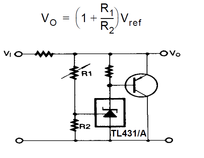
Explaining Programmable Shunt Regulator TL431, Datasheet, Application

zener voltage regulator circuit - theoryCIRCUIT - Do It Yourself